Industrial Plate Screens Perforations – Holes Shape, Aperture Size, Pitch, Arrangement
Designating various kinds of perforations and their arrangements in industrial perforated plate screens.
The perforation of a plate is designated by
— shape of the holes;
— aperture size w, or aperture sizes w1 and w2 in case of slots;
— mutual arrangements of holes;
— pitch p, or pitches p1 and p2 in cases where the pitches are different in directions parallel to the edges of the plate;
— orientation of the arrangement of the perforations relative to the edges of the plate.
Shape of holes – Perforations in Industrial Plate Screens
The shape of holes shall be designated by the following symbols:
- R: circular (round).
- C: square, with sides parallel to the edges of the plate.
- CD: square, with diagonals parallel to the edges of the plate.
- H: hexagonal.
- LR: slots with round ends.
- LC: slots with square ends.
Aperture size – Perforations in Industrial Plate Screens
Following the symbol for shape of hole, the aperture size shall be stated in millimetres.
- Aperture size of square or circular: W, Aperture size of slot: w1 × w2.
- W is the width of square or diameter of circular.
- w1 is the width of a slot, and w2 is the length of a slot.

Figure 1 — Code for shape of holes.

Figure 2 — Examples of coded shape of hole and aperture size
Arrangement of holes
Arrangement of holes includes U, Z, M, T, arrangements.
Pitch – Perforations in Industrial Plate Screens
For shapes R, C, CD or H in U- or Z-arrangements, both pitches shall be stated: p1 × p2.
- p1 is the shorter one pitche, and P2 is the longer.
- In the case of a U-arrangement, when p1 = p2, only p shall be stated.
- For M- or T-arrangements, only p shall be stated

Figure 3 — U-arrangement

Figure 4 — Z-arrangement
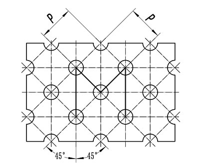
Figure 5 — M-arrangement
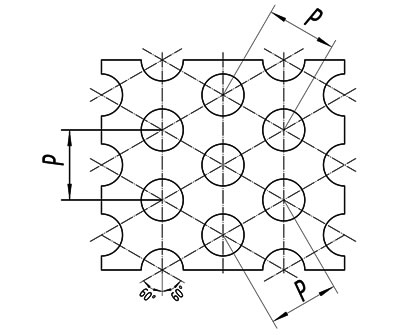
Figure 6 — T-arrangement

Figure 7 — Example R10 U15 × 20

Figure 8 — Example C5 Z10 × 20

Figure 9 — Example LR3 × 10 U12 × 18

Figure 10 — Example LC3 × 10 Z18 × 12

Figure 11 — Example C10 U20
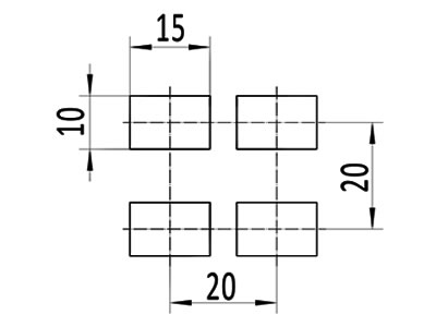
Figure 12 — Example LC10 × 15 U20
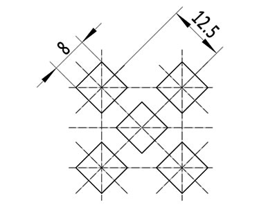
Figure 13 — Example CD8 M12.5
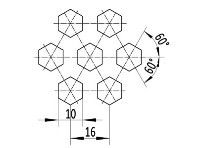
Figure 14 — Example H10 T16
Orientation of the perforation on the plate
The orientation of the perforations with the edges of the plate affects the performance as an industrial screen.
- T-arrangement
- Orientation 1 shall be with pitch p parallel to the longer edge (see Figure 15);
- Orientation 2 with p parallel to the shorter edge (see Figure 16).
- Shapes R, C, CD and H in U- and Z-arrangements
- Orientation 1 shall be with the shorter pitch p1 parallel to the longer edge (see Figure 17);
- Orientation 2 shall be with the shorter pitch parallel to the shorter edge (see Figure 18).
- Shapes LR and LC (slots) in U- or Z-arrangements
- Orientation 1 shall be with the width w1 parallel to the longer edge (see Figure 19);
- Orientation 2 shall be with the width w1 parallel to the shorter edge (see Figure 20).

Figure 15 — T-arrangement, Orientation 1
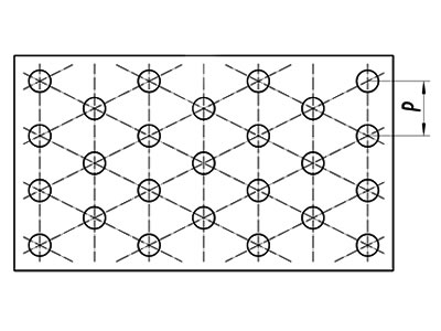
Figure 16 — T-arrangement, Orientation 2

Figure 17 — Example C5 Z10 × 18 Orientation 1

Figure 18 — Example C5 Z10 × 18 Orientation 2

Figure 19 — Example LR3 × 18 Z12 × 36 Orientation 1
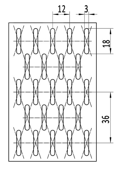
Figure 20 — Example LR3 × 18 Z12 × 36 Orientation 2